Cam Examples and Profiles PDF FILE - CLICK HERE FOR PRINTABLE WORKSHEET EXAMPLE USE OF A CAM Below is a typical use of a cam. We assume the follower axis is vertical.
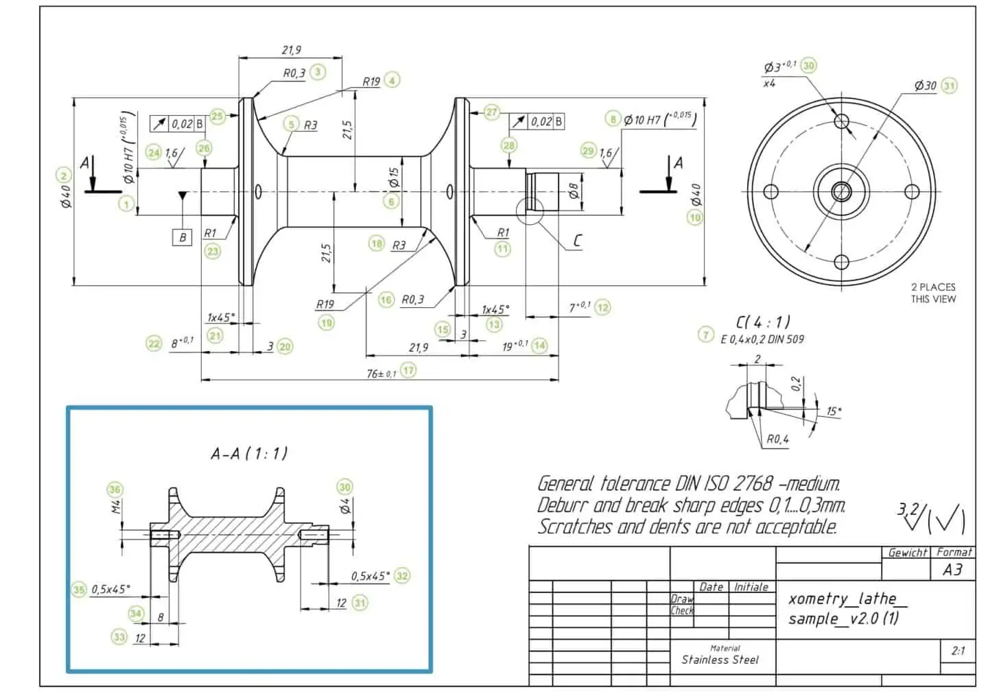
How To Prepare A Perfect Technical Drawing Xometry Europe
Draw a prime circle with center O and radius.

. This paper reviews the past and present research work in the field of kinematic and dynamic aspect of design and optimization of Cam profiles. Typically a simple grinding operation will produce the surface finish that is measured at 025 micron as a centre-line-average CLA. If you wish to maintain cam radius of curvature equal to a speci ed ˆ min then the base circle is given by R o ˆ min y y00 max 11 I will use a MATLAB script to design the cam and one portion of the script will compute equation 10 to nd the base circle radius.
Because designers first approach for cam profile optimization should be low acceleration jump. 1 Start Mastercam using your preferred method. PLOT THE DISPLACEMENT DIAGRAM 40mm 60 30 60 210 A G H P 0 1 2 3 4 5 6 0 1 2 3 4 5 6 B C D EF J K L M N 41.
2 Ro y s xcyc C. Draw the profile of the cam when cam rotates in clockwise direction. The Terminology of a Cam.
Draw a base circle with center O and radius equal to the minimum radius of the cam ie. As the cam rotates in an anticlockwise direction the follower falls diagram 2 and so does the arm of the toy. Work with live entities.
You can view a tutorial for creating a cam profile in AutoCAD that with a bit of patience will show the basics of how to generate your cam profiles either manually or by using CAD software. Cam cam proÞ le base circle xcam ycam P. Last edited by Kelly Bramble.
This video explains how to draw displacement diagram in case of follower motion with SHM. The mechanism of Cam and Follower is essential in the engineering field and has many different functions to the different machines. Enter the Base circle radius of the cam in mm 50 Enter the Height follower is needed to move in mm 50 Enter the number of motions follower as to complete in one cycle 3 Enter the Angle till where 1 Motion is followed Enter the Angle 180 Options for different follower motions are 1SHM 2DWELL 3UV Enter the type of 1 Motion is followed.
Along the ycam axis. Profile of the cam when the line of stroke of the valve rod passes through the axis of the cam shaft The profile of the cam as shown in Fig is drawn as discussed in the following steps. Then the Equations 5 and 6 are used to find the coordinates of xand yover a range of θ from 0 to2πradians for obtaining the cam profile.
The follower is shown at an angular displacement and corresponding lift y. Uniform acceleration retardation. A simple toy based on a cartoon character Ed the Handyman is controlled by a cam and follower.
There are normally three or four steps in any CADCAM process. It is the smallest circle of a cam profile drawn from the center of rotation of the cam. For designing a specific type of cam profile firstly the corresponding equations of S during the periods of lifting dwell at top position lowering and dwell at bottom position are replaced in Equation 7.
For a knife-edge BJCS Cam Profile Drawer is an application that can be used to drawer cams with a graph and manipulate it in many ways. Below are jpeg illustrations of the results. Httpsamznto3zWXHpXe-books for competitive exams.
The cam profile and the cam tappet interface are normally produced by grinding the surfaces. Lesson Goals Draw lines and arcs. 2 x X abs sin ω t ϕ where X is the follower maximum displacement ω is the cam angular velocity and ϕ.
2 Draw a circle shown as RAD Q equal to the least radius of the cam plus the radius of the roller and divide it into 30 divisions. How To Draw Cam. Mark the camshaft angles in the anticlockwise direction.
Drawing Vertical Lines In this exercise you start creating your part by drawing vertical construction lines. 5 MATLAB Script for Cam Design I will create a MATLAB script for design of this cam. This is the average height of the asperities on the surface.
3 Along each radial line plot the Y ordinates from the graph and at each point draw a 20 mm circle to represent the roller. This gure the cam rotates CW so when the mechanism is inverted the follower rotates CCW. 1 Draw the cam graph as shown.
Double-click Mastercams desktop icon. Useful links UPSC books. A part of cam profile is drawn during the out-stroke of follower.
In order to get low acceleration jump change of base circle radius nose radius valve lift angle maximum valve lift accto crank shaft angle will be obtained by using Matlab. A the axis of the follower passes through the axis of the cam shaft and b the axis of the follower is offset by 20 mm from the axis of the cam shaft. The radius of the base circle is Ro.
It is the surface area of a cam where follower touches. With the above given parameters a simulation run has been carried out when the cam profile is selected so as to generate a follower displacement x in the form. 12-15-2013 at 0838 AM.
Drawing the outer shape of the tutorial part.

How To Draw A Cam Profile Knife Edge Follower Part 4 Youtube

How To Draw Cam Profile Complete Construction Part 3 Youtube
Problems Based On Cam Profiles Solved Engg Tutorials
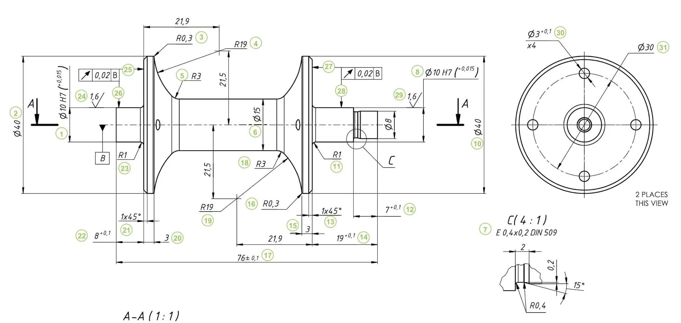
How To Prepare A Perfect Technical Drawing Xometry Europe

Cam And Follower Types Working Nomenclature Diagram Pdf

How To Draw A Cam Profile Knife Edge Follower Part 4 Youtube
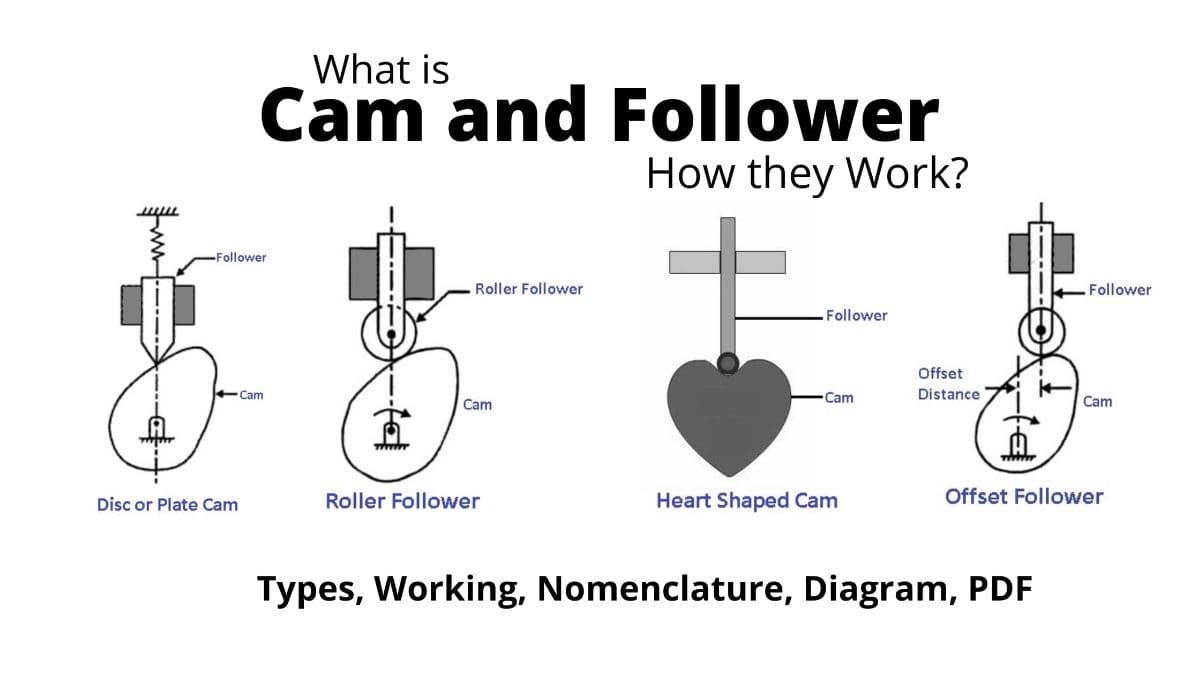
Cam And Follower Types Working Nomenclature Diagram Pdf
Cam Profile Profile How To Draw Cam Profile Cam Follower Kom Mechanical Youtube
0 comments
Post a Comment